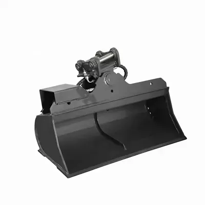
Tiltrotator controls are the operator's link to the tiltrotator's two hydraulic functions — tilt and rotation — and they directly affect productivity, grading accuracy, and operator fatigue. The standard configuration uses the excavator's existing auxiliary levers or pedals, which works for general use but lacks proportional precision and real-time angle feedback. The upgraded control system kit replaces standard levers with a proportional dual-axis joystick and adds a digital display showing exact tilt and rotation angles. Understanding how these systems work, their hydraulic and electrical requirements, and installation considerations helps operators and contractors choose the right control setup and avoid common pitfalls.
Standard Tiltrotator Controls
In the standard setup, the tiltrotator is controlled through the excavator's auxiliary hydraulic circuit. One lever or pedal controls tilt: actuating it one direction tilts the bucket left (up to 45°), the other tilts right (up to 45°). Tilt is double-acting — the operator can hold any angle within the ±45° range by maintaining lever position. A second lever or pedal controls rotation: actuating it one direction rotates the bucket clockwise, the other counterclockwise, with 360° continuous rotation in either direction.
The two functions can operate simultaneously — tilt and rotate at the same time — allowing the bucket to be positioned at any angle and orientation in one motion. This is what makes the tiltrotator so effective for grading, ditch cleaning, and precision shaping. Standard controls use on/off or proportional valves depending on the excavator's auxiliary circuit — some machines have proportional auxiliary control, others have on/off control with less precise modulation. Control quality varies significantly between brands and models. Standard controls don't provide real-time angle feedback — the operator estimates tilt and rotation visually, which can be imprecise for tight tolerances. For general excavation, backfilling, and rough grading, standard controls are usually enough; for precision grading, finish work, and operators who demand maximum accuracy, the upgraded system is recommended.
Proportional Joystick Control System
The optional control system kit replaces standard lever operation with a proportional dual-axis joystick that provides finer, more intuitive control over both tilt and rotation. Mounted on the operator's console, the joystick controls both functions through a single input: pushing left or right controls tilt (left tilts left, right tilts right, up to ±45°), and twisting the grip controls rotation (clockwise twist rotates clockwise, counterclockwise twist rotates counterclockwise, 360° continuous). The joystick is proportional — small movements produce small, slow adjustments; larger movements produce faster, larger adjustments. This proportional control is significantly more precise than on/off auxiliary levers, especially for fine grading and finish work where small, controlled adjustments are critical.
The joystick connects to proportional hydraulic valves installed in the tiltrotator's circuit, which regulate oil flow to the tilt cylinders and rotation motor based on joystick input. This provides smooth, modulated control rather than abrupt on/off action. The system also includes a digital display mounted in the cab, showing real-time tilt angle (±45°) and rotation position (0–360°). The display can be configured for degrees or percentage slope and may include presets for common angles. Digital feedback eliminates visual estimation, letting the operator match specified grades precisely. For precision grading, ditch work, or any task with tight angle tolerances, the combination of proportional joystick and digital display can dramatically improve both accuracy and speed. The kit is compatible with all TGEC tiltrotator models and can be installed as a factory option or field retrofit (professional installation required).
Hydraulic and Electrical Requirements
Both standard and upgraded controls have hydraulic requirements: the excavator must have a dedicated auxiliary circuit delivering the required flow (18–120 L/min depending on model) and pressure (210–220 bar) for continuous tilt and rotation. The circuit must support simultaneous operation of both functions. For the upgraded system, proportional valves are added — they must be compatible with the excavator's hydraulic system and the tiltrotator's flow/pressure specs. Verify hydraulic oil cooler capacity, as continuous operation generates extra heat.
Electrical requirements apply to the upgraded control system. It operates on 12V or 24V DC — verify the excavator's voltage and configure accordingly. The display and joystick need a dedicated power circuit with proper fuse protection. CAN bus integration is optional — it allows communication with the excavator's electronic system for features like automatic flow compensation, fault diagnostics, and display integration. CAN bus isn't required — the system works standalone with 12V/24V power and independent valves. Before installation, verify voltage, available fuse positions, and whether CAN bus integration is desired. Professional installation by a qualified hydraulic and electrical technician is strongly recommended — improper installation can cause control issues, electrical faults, or hydraulic damage.
Installation Considerations
Installing tiltrotator controls — especially the upgraded kit — requires careful planning and professional execution. For standard controls, installation is straightforward: connect the tiltrotator's hydraulic hoses to the excavator's auxiliary circuit, and use existing levers/pedals. No electrical work is needed. Verify the circuit delivers required flow and pressure, route hoses to avoid pinching or interference with arm movement and tilt/rotation range, and seal all connections properly.
For the upgraded kit, installation is more complex, involving both hydraulic and electrical work. Hydraulic installation: mount proportional valves in the circuit, run hoses to the tilt cylinders and rotation motor, connect valves to the auxiliary supply. Electrical installation: mount the joystick on the console, mount the display in the cab, run wiring from joystick and display to valves and power, install fuse protection, and configure voltage (12V/24V). If CAN bus integration is desired, connect to the excavator's CAN network and configure communication parameters. After installation, calibrate the system — joystick response, valve settings, and display must be calibrated per the manual. Test both functions through full ranges to verify smooth, accurate operation. Ensure the control system doesn't interfere with existing electronics and that safety interlocks function correctly. Professional installation by a qualified technician is strongly recommended. A tiltrotator compatibility guide provides more detail on matching the control system to specific excavator configurations.
Control System Maintenance and Troubleshooting
Standard controls require minimal maintenance — inspect hoses for wear and leaks, verify auxiliary flow and pressure, and ensure levers/pedals operate smoothly. For the upgraded kit, additional maintenance: inspect the joystick for smooth operation and proper response, check the display for correct readout and error codes, verify electrical connections for corrosion and looseness, inspect proportional valves for proper operation and leaks, and ensure hydraulic oil is clean and within spec (contaminated oil can damage valves and cause erratic control).
Common issues and troubleshooting: (1) erratic or unresponsive tilt/rotation — check flow and pressure, inspect valves for contamination, verify joystick calibration, check electrical connections; (2) display showing incorrect angles — recalibrate angle sensors, check sensor wiring, verify display configuration; (3) joystick not responding — check power and fuses, verify wiring, check for error codes, test joystick output; (4) slow tilt/rotation — verify flow meets requirement, check for restrictions or leaks, verify valves are fully opening; (5) system not powering on — check 12V/24V supply, verify fuses, check main power connections, test control module; (6) CAN bus errors — verify CAN wiring and connections, check baud rate and address configuration, ensure compatibility with the excavator's CAN protocol. For persistent issues, contact TGEC technical support with tiltrotator model, control system serial number, excavator make/model, and issue description. Regular maintenance — clean electrical connections, clean hydraulic oil, regular calibration checks — ensures consistent performance and extends service life.